This chapter gives an example on how to configure the Oscilloscope module to be used with a target application implementing a Night mode switch with a light sensor. Although this example only utilizes the SPI interface as data source, the procedure will be the same for all data sources. The target code used in this example and a description of the hardware setup can be found in Oscilloscope Example Code.
Todo: Select correct tool in the
DGI Control Panel.
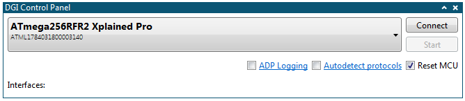
Todo: Click
Connect to make a connection to the DGI on the selected
tool.
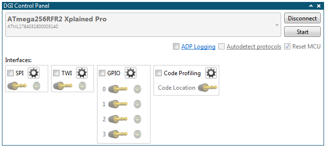
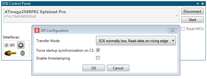
Todo:
- Click the SPI checkbox
- Open the SPI Configuration dialog by clicking the Gear button next to the SPI checkbox
Todo:
- Open the configuration panel
- Add an Oscilloscope module to the Data Visualizer
- Drag the source connector from the interface in the DGI Control Panel into the sink for the oscilloscope channel to make a connection
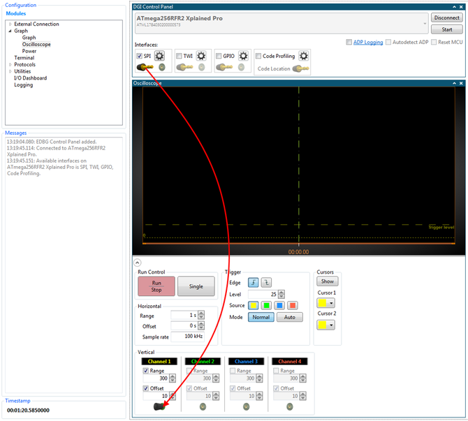
The Oscilloscope module can now
be used to analyze the data acquired from the light sensor when toggling a desk lamp ON
and OFF above the I/O1 Xplained Pro.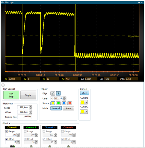 By turning on the Cursors it is possible to measure the
time it takes for the lamp to settle in the ON state. In this case, it took about 300 ms
(ΔX in the plot area). Zooming further in on the plot makes
it possible to use the cursors to measure the frequency of the light flickering. The
1/ΔX field in the plot area shows that the frequency is about
100 Hz, which matches well with the 50 Hz AC power of the lamp (the power switches
polarity 100 times per second).
By turning on the Cursors it is possible to measure the
time it takes for the lamp to settle in the ON state. In this case, it took about 300 ms
(ΔX in the plot area). Zooming further in on the plot makes
it possible to use the cursors to measure the frequency of the light flickering. The
1/ΔX field in the plot area shows that the frequency is about
100 Hz, which matches well with the 50 Hz AC power of the lamp (the power switches
polarity 100 times per second).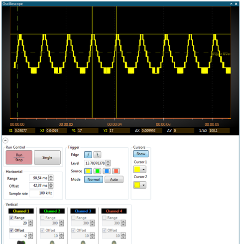
Todo:
After some adjustments of the trigger level by dragging it with the mouse in the
oscilloscope plot area, and zooming in on the plot by adjusting the
Horizontal and Vertical range, a lamp
switch on event could look something like the picture below.- Set sample rate to 100 kHz
- Enable Trigger on falling Edge and set Mode to Normal
- Push Start in the DGI Control Panel
- Push the Run-Stop button in the Oscilloscope module