The SPI interface source contains the raw
values received on the SPI interface. The sink sends values received
back out on the SPI bus. For further details on the physical part of the SPI interface, see
the user guide of the debugging tool to be used to sample the SPI data.
Important: If the SPI
sink is connected to a source with a
multibyte type, the byte order may be unpredictable.
Important: The SPI hardware module uses an
active-low Chip Select (CS) signal. Any data sent when the CS pin is high will be
ignored.
The SPI Configuration dialog is opened from the SPI interface in the DGI control panel.
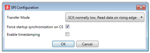
| Field Name | Values | Usage |
|---|---|---|
| Transfer Mode |
|
SPI mode, controlling clock phase and sampling. |
| Force synchronization on CS | ON or OFF | The SPI interface is only enabled after the Chip Select line has toggled twice. |
| Enable timestamping | ON or OFF | Data is timestamped through the DGI timestamp interface (yields a slower transfer rate). |