1. See NVM User Row Mapping table for the BODVDD default value settings.
2. These values are based on simulation. These values are not covered by test limits in production or characterization.
Figure 1. BODVDD Hysteresis OFF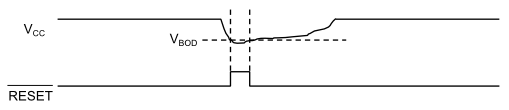
Figure 2. BODVDD Hysteresis ON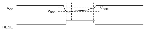
| Symbol | Parameters | Conditions | Min | Typ | Max | Unit |
|---|---|---|---|---|---|---|
| VBOD+ | BODVDD high threshold Level | VDD level, Bod setting = 8 (default) | - | 2,86 | - | V |
| VDD level, Bod setting = 9 | - | 2,92 | - | |||
| VDD level, Bod setting = 44 | - | 4,57 | - | |||
| VBOD- / VBOD | BODVDD low threshold Level | VDD level, Bod setting = 8 (default) | - | 2,8 | - | |
| VDD level, Bod setting = 9 | - | 2,85 | - | |||
| VDD level, Bod setting = 44 | - | 4,51 | - | |||
| Step size | - | 60 | - | mV | ||
| VHys | Hysteresis (VBOD+ - VBOD-) BODVDD.LEVEL = 8 to 48 | VDD | 40 | - | 75 | mV |
| Tstart | Startup time | time from enable to RDY | - | 3,1 | - | µs |
- These are based on characterization.
| Symbol | Parameters | Conditions | Ta | Typ. | Max | Units |
|---|---|---|---|---|---|---|
| IDD | IDLE, Mode CONT | VDD = 2.7V |
Max 85°C Typ 25°C |
40.9 | µA | |
| VDD = 5.0V | 43.1 | |||||
| IDLE, Mode SAMPL | VDD = 2.7V | 0.1 | ||||
| VDD = 5.0V | 0,1 | |||||
| STANDBY, Mode SAMPL | VDD = 2.7V | 3.6 | ||||
| VDD = 5.0V | 3.2 |
- These are based on characterization.