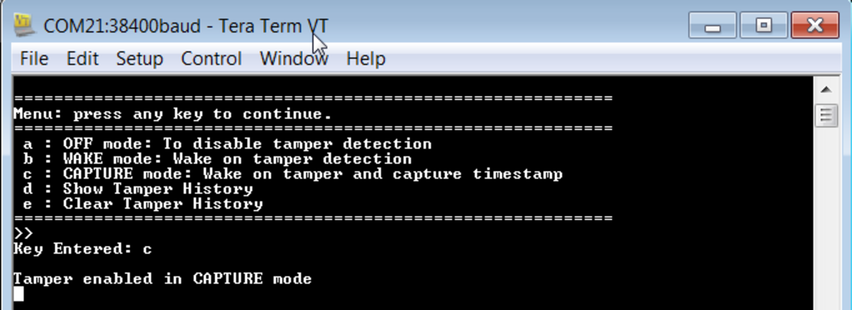
- When the key “c” is entered, the
terminal window will appear as shown in the following figureFigure 1. Terminal Window when Tamper Enabled in Capture Mode
- The device will enable tamper detection in capture mode (for more details, refer Modes of Operation) and enable the RTC
- After enabling the RTC, the firmware configures the DMA for getting the timestamp from the TIMESTAMP register without CPU intervention; the clock starts counting at an interval of 1 second
- Set the mode flag and the previous mode flag as SET_TO_CAPTURE, to keep track of the current operating mode of tamper and previous mode of tamper
- The device goes to sleep. However, the RTC will still be running internally.
- Now, the firmware will be waiting for the tamper input in the main function. In this condition the user also has the provision to change the input mode (only after the first tamper condition is detected).
- Here, the Tamper condition can be generated by pressing and leaving the user switch SW0 (which is connected to the tamper input pin)
- When the tamper occurs, the following
action happens:
- Get the current time from the clock register and set the alarm after five seconds and Set the tamper flag
- Now the time value is available in the structure variable tamper_time. It prints the time on terminal window as shown in the following figure.
-
The format in which the time is printed on the terminal window, is given as follows
[HH:MM:SS] = [12:00:00] PM
Figure 2. Terminal Window when Tamper Callback occured in Capture Mode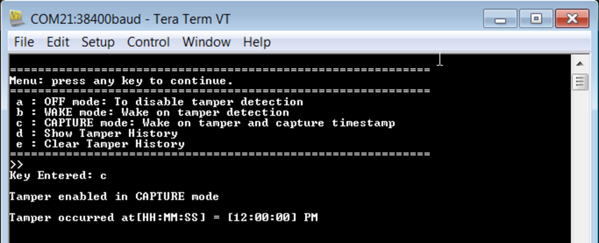
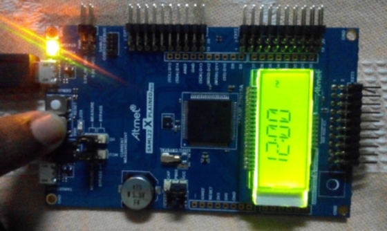
- Display the tamper occurred
time on the LCD as shown in the following figure and enable the timer module
with specified overflow value (user configurable) for blinking the SLCD
backlight by toggling the port pin connected to itNote: The LCD displays only Hours: Minutes as 12:00 PM (for seconds, view the terminal window)Figure 3. LCD Screen when Tamper Occurred in Capture Mode
- In addition to the above, it also writes the tamper Timestamp value to the RWW EEPROM section for keeping track of the tamper occurance
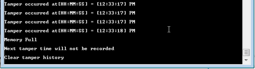
- The application is configured
to store only 128 entries of time. When 128 entries are filled the firmware
will display the error message shown in the following figure.Figure 4. Memory Full Error Message