The debugger consists of an internal main board and an external Micro-B USB
connector and an 8-pin SIL connector. On the front of the debugger enclosure is an
indicator light strip and a hidden push button located underneath the logo.
Figure 1. MPLAB® PICkit™ 4 In-Circuit
Debugger
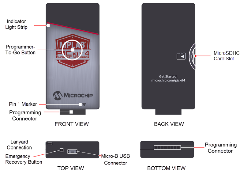
- 1.Lanyard Connection - An opening through the top and side for a lanyard (not included) to be attached.
- 2.Emergency Recovery Button - If needed, this recessed button is used for Recovery Boot Mode.
- 3.Micro-B USB Connector - Used to connect the debugger to the computer with the supplied USB cable.
- 4.Indicator Light Strip - Displays the operational modes of the debugger (see Indicator Lights Strip).
- 5.Button Area - The area in the center of the shield logo is used for the Programmer-To-Go1 option and for invoking the bootloader mode (see How to Invoke the Bootload Mode).
- 6.Pin 1 Marker - This designates the pin 1 location for proper connector alignment.
- 7.Programming Connector - The connector is an 8-pin SIL header (0.100" spacing) that connects to the target device (see Pinouts for Interfaces).
- 8.MicroSDHC Card Slot1 - The microSDHC card slot supports a large variety of microSDHC cards with various speed requirements.
Note: 1 The functionality
will be available in a future firmware update of the product through MPLAB X
IDE.