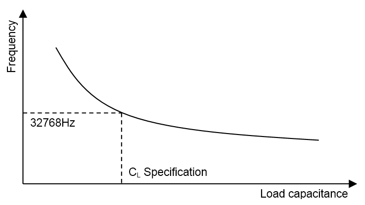
The crystal frequency is dependent on the capacitive load applied, as shown by Figure 3. Applying the capacitive load specified in the crystal data sheet will provide a frequency very close to the nominal frequency of 32768 Hz. If other capacitive loads are applied, the frequency will change. The frequency will increase if the capacitive load is decreased, and will decrease if the load is increased, as shown in Figure 2.
The frequency pull-ability or bandwidth—how far from the nominal frequency the resonant frequency can be forced by applying load—depends on the Q-factor of the resonator. The bandwidth is given by the nominal frequency divided by the Q-factor, and for high-Q quartz crystals, the usable bandwidth will be very limited. If the measured frequency deviates from the nominal frequency, the oscillator will be less robust. This is due to higher attenuation in the feedback loop β(jω) that will cause a higher loading of the amplifier A to achieve unity gain (see Figure 1).
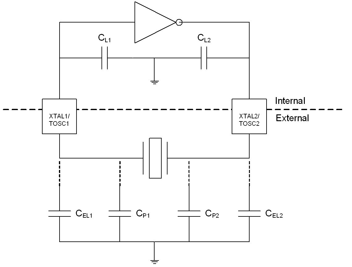
A good way of measuring the effective load capacitance (the sum of load capacitance and parasitic capacitance) is to measure the oscillator frequency and compare it to the nominal frequency of 32768 Hz. If the measured frequency is close to 32768 Hz, the effective load capacitance will be close to the specification. This can be done using the firmware supplied with this application note and a standard 10X scope probe on the clock output on an I/O pin, or, if available, measuring the crystal directly with a high-impedance probe intended for crystal measurements. More details can be found in Chapter 4, Test Firmware.
Without external capacitors, the total load capacitance will be given by Figure 3. In some cases, external capacitors (CEL1 and CEL2) must be added to match the capacitive load specified in the crystal’s data sheet. If external capacitors are used, the total capacitive load will be given by Figure 4.