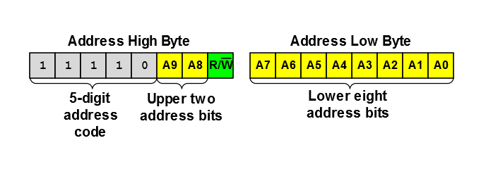
In 10-bit Addressing modes, the first two bytes following a Start condition
form the 10-bit address (see figure below). The first byte (address high byte) holds the
upper two address bits, the R/W bit, and a five digit code
(11110) as defined by the I2C Specification. The second
byte (address low byte) holds the lower eight address bits. In all 10-bit Addressing
modes, the R/W value contained in the first byte must always be
zero (R/W = 0). If the master intends to read
data from the slave, it must issue a Restart condition, followed by the address high
byte with R/W set (R/W =
1).
The first byte is compared to the values in the I2CxADR1 and I2CxADR3 registers in 10-bit Addressing mode, or
to the masked value of I2CxADR1 in 10-bit Addressing with Masking mode. The second byte
is compared to the values in the I2CxADR0 and I2CxADR2 registers in 10-bit Addressing mode, or to the masked value of
I2CxADR0 in 10-bit Addressing with Masking mode. If an address high byte match occurs,
the high address byte is copied to I2CxADB1 and the R/W bit value is copied to the
Read Information (R) bit, and if an address low byte match occurs, the low address
byte is copied to I2CxADB0.
Figure 1. Upper and Lower 10-Bit Address
Bytes