The I2C module provides a synchronous serial interface between the microcontroller and other I2C-compatible devices using a bidirectional two-wire bus. Devices operate in a master/slave environment that may contain one or more master devices and one or more slave devices. The master device always initiates communication.
The I2C bus consists of two signal connections:
- Serial Clock (SCL)
- Serial Data (SDA)
Both the SCL and SDA connections are open-drain lines, each line requiring
pull-up resistors to the application’s supply voltage. Pulling the line to ground is
considered a logic ‘0’, while allowing the line to float is considered
a logic ‘1’. It is important to note that the voltage levels of the
logic low and logic high are not fixed and are dependent on the bus supply voltage.
According to the I2C Specification, a logic low input level is up to 30% of
VDD (VIL ≤ 0.3VDD), while the logic high input
level is 70% to 100% of VDD (VIH ≥ 0.7VDD). Both signal
connections are considered bidirectional, although the SCL signal can only be an output
in Master mode and an input in Slave mode.
All transactions on the bus are initiated and terminated by the master device. Depending on the direction of the data being transferred, there are four main operations performed by the I2C module:
- Master Transmit: master is transmitting data to a slave
- Master Receive: master is receiving data from a slave
- Slave Transmit: slave is transmitting data to a master
- Slave Receive: slave is receiving data from a master
The I2C interface allows for a multi-master bus, meaning that there can be several master devices present on the bus. A master can select a slave device by transmitting a unique address on the bus. When the address matches a slave’s address, the slave responds with an Acknowledge condition (ACK), and communication between the master and that slave can commence. All other devices connected to the bus must ignore any transactions not intended for them.
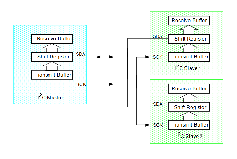
The following figure shows a typical I2C bus configuration with one master and two slaves.