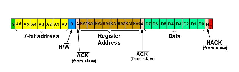
- I2C Master mode with 7-bit addressing
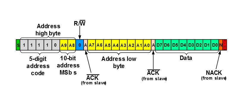
- I2C Master mode with 10-bit addressing
Once Master hardware has determined that the bus is free (BFRE =
1), it examines the state of the Address Buffer Disable (ABD) bit. The ABD bit determines whether the I2CxADB registers
are used.
When ABD is clear (ABD = 0), address buffers I2CxADB0 and I2CxADB1 are active. In 7-bit Addressing mode,
software loads I2CxADB1 with the 7-bit slave address and R/W
bit setting, and also loads I2CxTXB with the first byte of data . In 10-bit
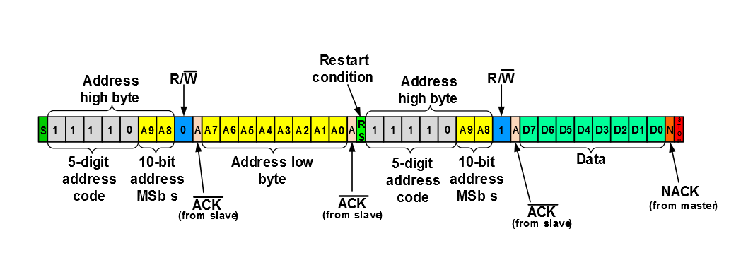
Addressing mode, software loads I2CxADB1 with the address high byte and I2CxADB0 with
the address low byte, and also loads I2CxTXB with the first data byte. Software must
issue a Start condition to initiate communication with the slave.
1), the address buffers are inactive. In
this case, communication begins as soon as software loads the slave address into
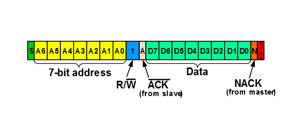
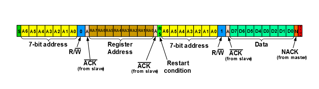
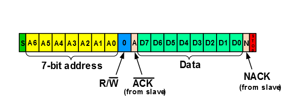
I2CxTXB. Writes to the Start bit (S) are ignored.In 7-bit Addressing mode, the Least Significant bit (LSb) of the 7-bit address byte acts as the Read/not Write (R/W) information bit, while in 10-bit Addressing mode, the LSb of the address high byte is reserved as the R/W bit. When R/W is set, the master intends to read data from the slave (see figure below). When R/W is clear, the master intends to write data to the slave (see figure below). The master may also wish to read or write data to a specific location, such as writing to a specific EEPROM location. In this case, the master issues a Start condition, followed by the slave’s address with the R/W bit clear. Once the slave acknowledges the address, the first data byte following the 7-bit or 10-bit address is used as the slave’s specific register location. If the master intends to read data from the specific location, it must issue a Restart condition, followed by the slave address with the R/W bit set (see figure below). If the addressed slave device exists on the bus, it must respond with an Acknowledge (ACK) sequence.
Once a slave has acknowledged its address, the master begins to receive data from the slave or transmits data to the slave. Data is always transmitted Most Significant bit (MSb) first. When the master wishes to halt further communication, it transmits either a Stop condition, signaling to the slave that communication is to be terminated, or a Restart condition, informing the bus that the current master wishes to hold the bus to communicate with the same or other slave devices.